How to make a quick animated similar to touch led using Arduino ?.

I think this is a very good project for the beginners to learn Arduino as well as to design PCB for this project and make it a fully customized Module. Let's get started...
Before I proceed to explain these project you require the following thing.
- Arduino Uno
- RGB Led(common anode)
- Resistor 330ohm, 10k ohm
- Soldering iron
- Male strip -1
- Push Button-1
- Proteus and Arduino software
1. INSTALLATION OF SOFTWARE AND SIMULATION
1. Install the latest proteus in your PC
2. Add Arduino library in Proteus.
3.After installation creates a new project and makes the schematic as follows.

4. Install Arduino in your pc.
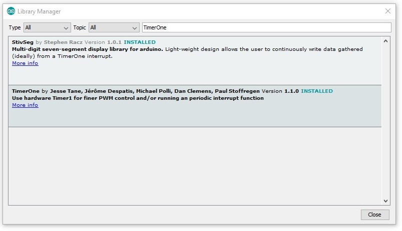
5. Add TimerOne library in Arduino.(Sketch ->Include Library -> Manage Libraries ->

6. Now write the following code in Arduino then Compile and generate hex file.
#include <TimerOne.h>
const int button = 8;
const int yellow = 9;
const int red = 11;
signed int flag = 0;
volatile signed long count = 0;
int buttonState = 0;
int lastButtonState = 0;
void setup() {
DDRC = 0xfe;
PORTC = 0x00;
TCCR2A = 0x00;
TCCR2B = 0x00;
pinMode(8, OUTPUT);
pinMode(9, OUTPUT);
pinMode(10, OUTPUT);
pinMode(11, OUTPUT);
pinMode(12, OUTPUT);
digitalWrite(12, HIGH);
digitalWrite(10, LOW);
pinMode(button, INPUT);
Serial.begin(9600);
digitalWrite(red, LOW);
digitalWrite(yellow, LOW);
Timer1.initialize(150000);
Timer1.attachInterrupt(counter);
}
void loop() {
noInterrupts();
flag = count;
interrupts();
Serial.println(flag);
delay(150);
ledglow();
}
void ledglow() {
digitalWrite(yellow, LOW);
digitalWrite(red, LOW);
int odd = flag % 7;
switch (odd) {
Serial.println(odd);
case 0:
digitalWrite(yellow, LOW);
digitalWrite(red, LOW);
break;
case 1:
digitalWrite(yellow, HIGH);
digitalWrite(red, LOW);
break;
case 2:
digitalWrite(yellow, LOW);
digitalWrite(red, HIGH);
break;
case 3:
digitalWrite(yellow, HIGH);
delay(100);
digitalWrite(yellow, LOW);
delay(100);
digitalWrite(red, HIGH);
delay(100);
digitalWrite(red, LOW);
break;
case 4:
digitalWrite(yellow, HIGH);
delay(100);
digitalWrite(yellow, LOW);
delay(50);
digitalWrite(yellow, HIGH);
delay(100);
digitalWrite(yellow, LOW);
delay(50);
digitalWrite(yellow, HIGH);
delay(100);
digitalWrite(yellow, LOW);
delay(50);
digitalWrite(yellow, HIGH);
delay(100);
digitalWrite(yellow, LOW);
delay(50);
digitalWrite(red, HIGH);
delay(100);
digitalWrite(red, LOW);
delay(50);
digitalWrite(red, HIGH);
delay(100);
digitalWrite(red, LOW);
delay(50); digitalWrite(red, HIGH);
delay(100);
digitalWrite(red, LOW);
delay(50); digitalWrite(red, HIGH);
delay(100);
digitalWrite(red, LOW);
delay(50); digitalWrite(red, HIGH);
delay(100);
digitalWrite(red, LOW);
delay(50); digitalWrite(red, HIGH);
delay(100);
digitalWrite(red, LOW);
delay(50);
break;
case 5:
for (int i = 100; i >= 0; i -= 5) {
digitalWrite(red, HIGH);
digitalWrite(yellow, HIGH);
delay(i);
digitalWrite(red, LOW);
digitalWrite(yellow, LOW);
delay(i);
}
break;
case 6:
for (int i = 100; i >= 0; i -=5) {
digitalWrite(red, HIGH);
delay(i);
digitalWrite(red, LOW);
delay(i);
}
break;
}
}
int counter() {
buttonState = digitalRead(button);
if (buttonState != lastButtonState) {
if (buttonState == HIGH) {
count++;
Serial.println("on");
Serial.print("number of button pushes: ");
Serial.println(count);
} else {
Serial.println("off");
}
delay(50);
}
lastButtonState = buttonState;
return count;
}
How to get hex file in Arduino?
The hex file is converted as part of the Verify (Compile) process.
Select File: Preferences, check the Verbose output in Arduino software
When you compile the last 2 lines that are displayed are:
C:\Users\Owner\AppData\Local\Temp\build1191639898936270974.tmp\eightx32display_progmem_eeprom.cpp.hex
Binary sketch size: 8,362 bytes (of a 130,048 byte maximum)
And there's your hex file

7. Copy the hex path and paste in the Arduino which is opened in the Proteus.

8. Now start the simulation

9. Now press the push button and check different type of animation if everything works then move towards hardware and PCB designing.
2. HARDWARE IMPLEMENTATION
1. Take a small piece of rectangular PCB and mount RGB led, Button, Male strip, and resistors according to your wish.

2. Do the connection from the proteus schematics or from the above diagram(330-ohm resistor is shorted in the above diagram because our module give very dimmed light so you can also short the resistor if led is dimmed)
3. Place the module on the Arduino and dump the Arduino program in Arduino after that press the button and see the different type of animation.

4 Now create your animation.
ENJOY YOUR PRESSED LED...
Any queries? comment below.

#include <TimerOne.h>
const int button = 8;
const int yellow = 9;
const int red = 11;
signed int flag = 0;
volatile signed long count = 0;
int buttonState = 0;
int lastButtonState = 0;
void setup() {
DDRC = 0xfe;
PORTC = 0x00;
TCCR2A = 0x00;
TCCR2B = 0x00;
pinMode(8, OUTPUT);
pinMode(9, OUTPUT);
pinMode(10, OUTPUT);
pinMode(11, OUTPUT);
pinMode(12, OUTPUT);
digitalWrite(12, HIGH);
digitalWrite(10, LOW);
pinMode(button, INPUT);
Serial.begin(9600);
digitalWrite(red, LOW);
digitalWrite(yellow, LOW);
Timer1.initialize(150000);
Timer1.attachInterrupt(counter);
}
void loop() {
noInterrupts();
flag = count;
interrupts();
Serial.println(flag);
delay(150);
ledglow();
}
void ledglow() {
digitalWrite(yellow, LOW);
digitalWrite(red, LOW);
int odd = flag % 7;
switch (odd) {
Serial.println(odd);
case 0:
digitalWrite(yellow, LOW);
digitalWrite(red, LOW);
break;
case 1:
digitalWrite(yellow, HIGH);
digitalWrite(red, LOW);
break;
case 2:
digitalWrite(yellow, LOW);
digitalWrite(red, HIGH);
break;
case 3:
digitalWrite(yellow, HIGH);
delay(100);
digitalWrite(yellow, LOW);
delay(100);
digitalWrite(red, HIGH);
delay(100);
digitalWrite(red, LOW);
break;
case 4:
digitalWrite(yellow, HIGH);
delay(100);
digitalWrite(yellow, LOW);
delay(50);
digitalWrite(yellow, HIGH);
delay(100);
digitalWrite(yellow, LOW);
delay(50);
digitalWrite(yellow, HIGH);
delay(100);
digitalWrite(yellow, LOW);
delay(50);
digitalWrite(yellow, HIGH);
delay(100);
digitalWrite(yellow, LOW);
delay(50);
digitalWrite(red, HIGH);
delay(100);
digitalWrite(red, LOW);
delay(50);
digitalWrite(red, HIGH);
delay(100);
digitalWrite(red, LOW);
delay(50); digitalWrite(red, HIGH);
delay(100);
digitalWrite(red, LOW);
delay(50); digitalWrite(red, HIGH);
delay(100);
digitalWrite(red, LOW);
delay(50); digitalWrite(red, HIGH);
delay(100);
digitalWrite(red, LOW);
delay(50); digitalWrite(red, HIGH);
delay(100);
digitalWrite(red, LOW);
delay(50);
break;
case 5:
for (int i = 100; i >= 0; i -= 5) {
digitalWrite(red, HIGH);
digitalWrite(yellow, HIGH);
delay(i);
digitalWrite(red, LOW);
digitalWrite(yellow, LOW);
delay(i);
}
break;
case 6:
for (int i = 100; i >= 0; i -=5) {
digitalWrite(red, HIGH);
delay(i);
digitalWrite(red, LOW);
delay(i);
}
break;
}
}
int counter() {
buttonState = digitalRead(button);
if (buttonState != lastButtonState) {
if (buttonState == HIGH) {
count++;
Serial.println("on");
Serial.print("number of button pushes: ");
Serial.println(count);
} else {
Serial.println("off");
}
delay(50);
}
lastButtonState = buttonState;
return count;
}


This is amazing project for Beginners
ReplyDelete